Web User Interface - DALI Commissioning
DALI Commissioning
Lamps
This page displays the list of commissioned lamps. The list provides a descriptive Name of each lamp as well as other information like Actual Level, Type and short address S.A..
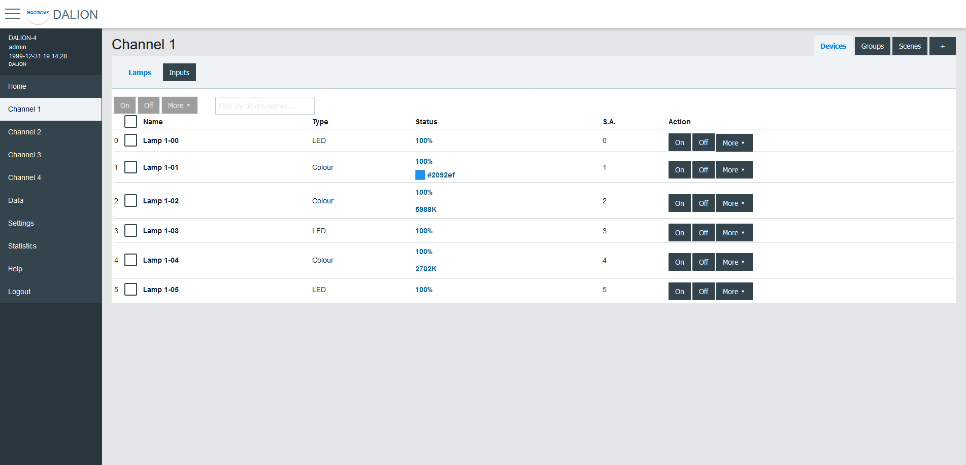
Lamps can be turned On, Off or we can Set Level in a percentage of its light intensity. Notify helps to identify a lamp by dimming it in a loop between its minimum and maximum light intensity. Unassign removes the lamp from the list of lamps while Delete also removes the lamp from the list, but also resets its DALI parameters to the default values.
For the lamps with colour control, available with DALI Type 8 (DT8) lamps, the current colour can be modified with Set Colour.
By clicking on a lamp row, the Lamp Parameters page opens.
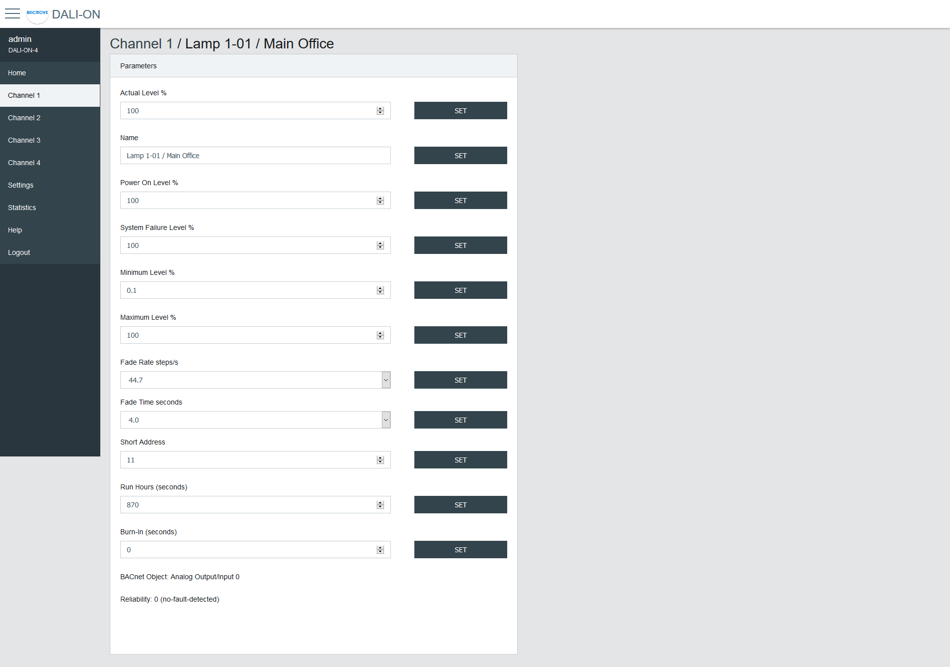
Lamp Parameters
This page allows the configuration of lamp parameters.
| Name | Unit | Minimum | Maximum | Default | Description |
|---|---|---|---|---|---|
| Actual Level | Percent | 0% | 100% | Actual light intensity | |
| Name | String | 32 characters | Name of the lamp | ||
| Power On Level | Percent | 0% | 100% | 100% | Level of intensity after a power on |
| System Failure Level | Percent | 0% | 100% | 100% | Level of intensity when system failure |
| Minimum Level | Percent | 0.1% | 100% | 100% | Minimum level of intensity |
| Maximum level | Percent | 0.1% | 100% | 100% | Maximum level of intensity |
| Fade Rate | Choice | 2.8 | 358 | 44.7 | Fade rate in steps per second |
| Fade Time | Choice | No Fade | 90.5 | No Fade | Fade time in seconds |
| Short Address | Number | 0 | 63 | The short address | |
| Run Hours | Number | 0 | 65535 | 0 | Number of seconds where the lamp was on |
| Nominal Power | Number | 0 | 4294967 | 0 | Nominal power |
| Burn-In | Number | 0 | 65535 | 0 | Number of seconds remaining to the burn-in |
| Dimming Curve | Choice | Logarithmic | Linear | Logarithmic | Dimming curve |
| Energy Usage Accumulated | Number | 0 | 42949672 | 0 | Energy usage accumulated |
| BACnet Object | The BACnet object associated with the lamp | ||||
| Reliability | Reliability of the lamp |
Emergency Parameters
For the lamps of the type "Self-contained emergency lighting (device type 1)", other parameters are available. When emergency parameters are available, a tab Emergency is added.
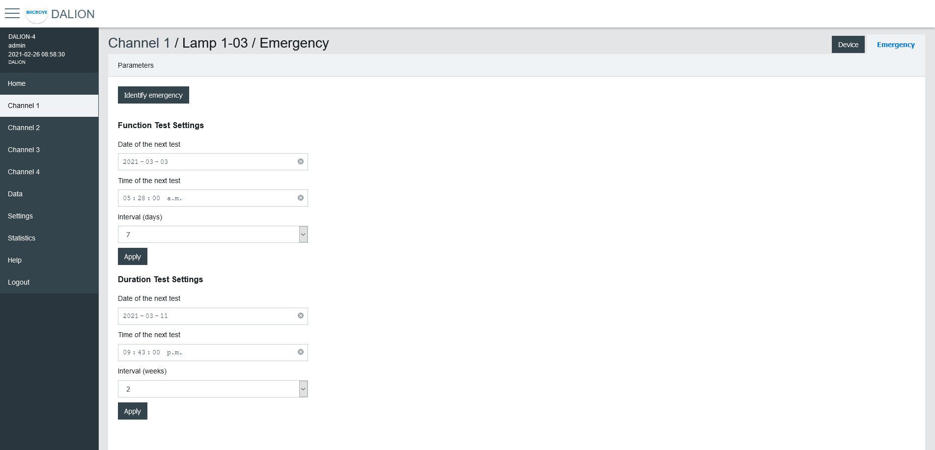
Identify emergency
Allows for the identification of the emergency lamp.
Function Test Settings
Allows the configuration of the interval for the function test.
Duration Test Settings
Allows the configuration of the interval for the duration test.
Prolong
Allows for the configuration of the prolong time.
Features
Show the features bits values.
Emergency Mode
Show the emergency mode bits value.
Emergency Status
Show the emergency status bits value.
Failure Status
Show the failure status bits value.
Timings
Show to values of the timings.
Other modes
Allows modifying the inhibit and rest modes.
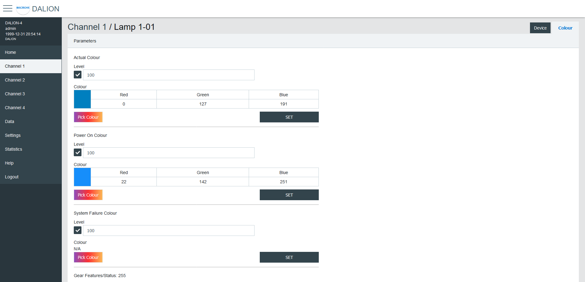
Colour Parameters
For the lamps with colour control, available with DALI Type 8 (DT8) lamps, other parameters are available. When colour parameters are available, a tab Colour is added.
| Name | Description |
|---|---|
| Actual Colour | Actual colour |
| Power On Colour | Colour after a power on |
| System Failure Colour | Colour when system failure |
| Gear Features/Status | DALI features of the lamp |
| Colour Type Features | DALI colour features of the lamp |
| Scenes 1-16 | Colour for the scenes 1 to 16 |
| Tc Warmest Kelvin (1) | Warmest colour temperature in Kelvin |
| Tc Coolest Kelvin (1) | Coolest colour temperature in Kelvin |
| Tc Physical Warmest (1) | Physical warmest colour temperature in Kelvin |
| Tc Physical Coolest (1) | Physical coolest colour temperature in Kelvin |
| RGBWAF Control (2) | RGBWAF Control |
| RGBWAF Assigned Colour (2) | RGBWAF Assigned Colour |
(1) Only available for lamps with the colour type; colour temperature Tc.
(2) Only available for lamps with the colour type; RGBWAF.
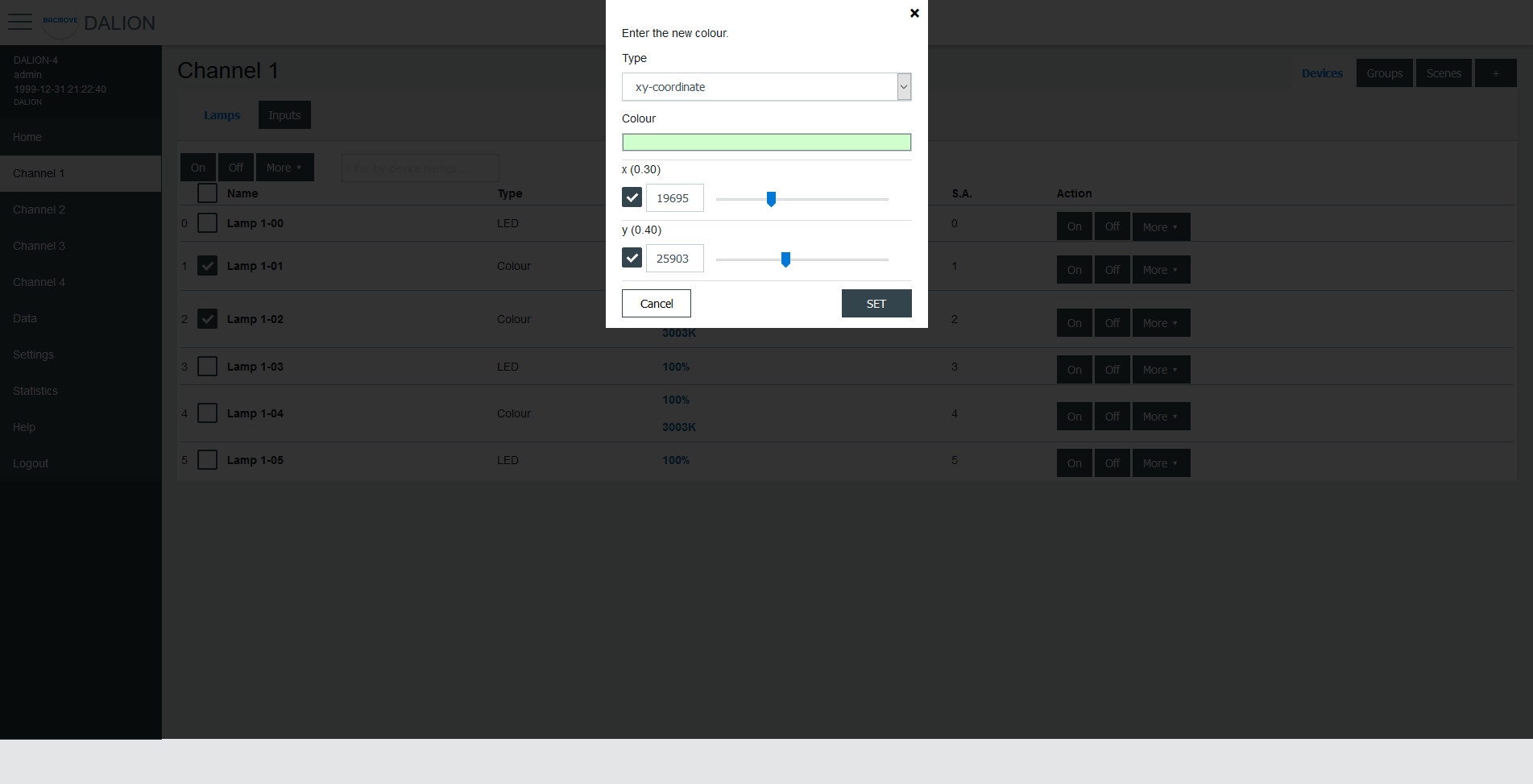
Colour Picker
When using Set Colour menu or the Pick Colour button a window appear to allow choosing the desired colour.
The window allows defining the colour according to the types of colours available for the selected lamp.
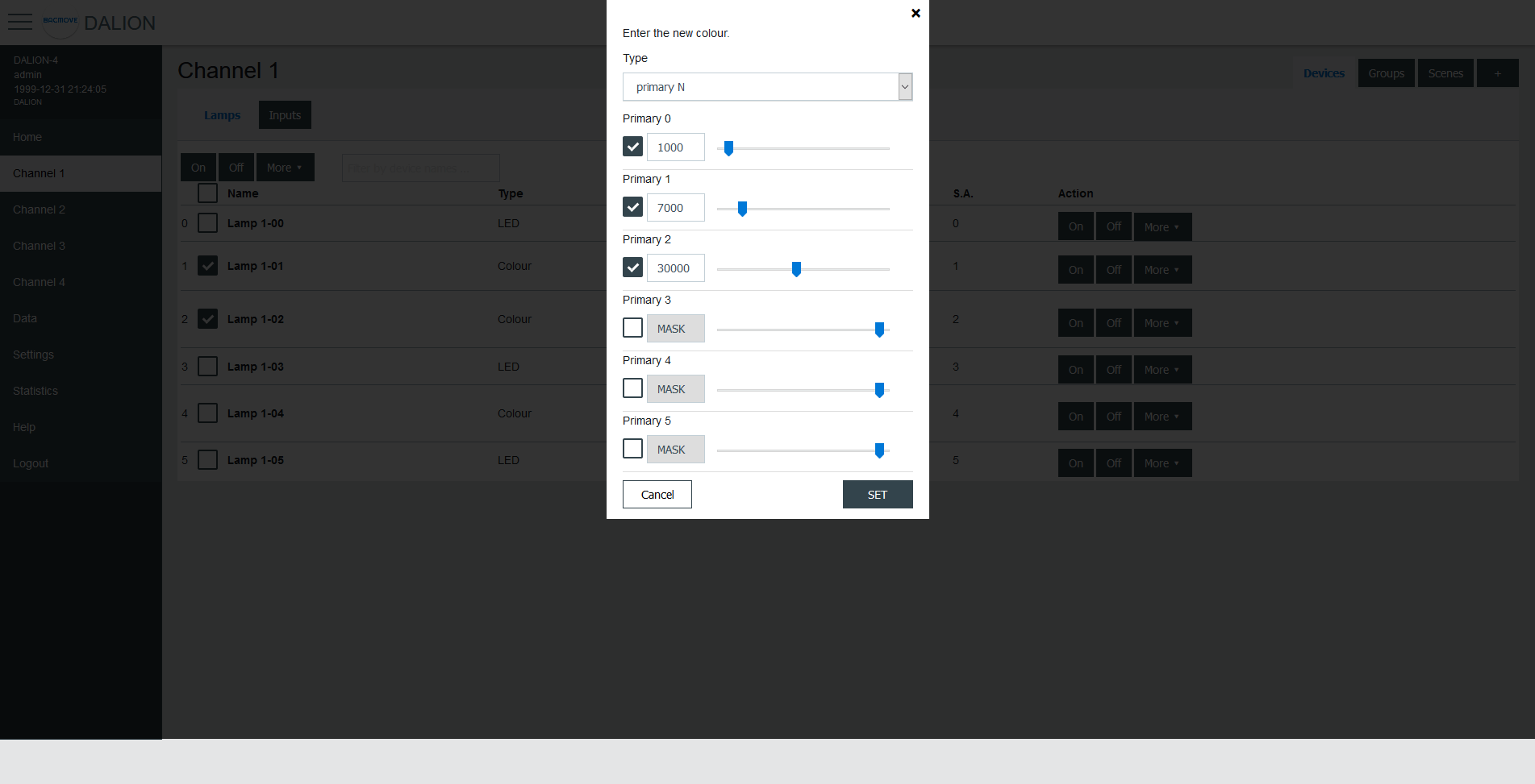
When a value is MASK, this value is not modified.
For example, it is possible to set only the green colour, without affecting the red and blue colour.
xy-Coordinate
| Name | Unit | Minimum | Maximum | Default | Description |
|---|---|---|---|---|---|
| Colour Preview (1) | RGB | Clicking on the colour will open the browser colour picker. | |||
| x | 1 / 65536 | 0 | 65534 | ||
| y | 1 / 65536 | 0 | 65534 |
(1) Colour is for demonstration purposes only, the resulting lamp colour may be different.
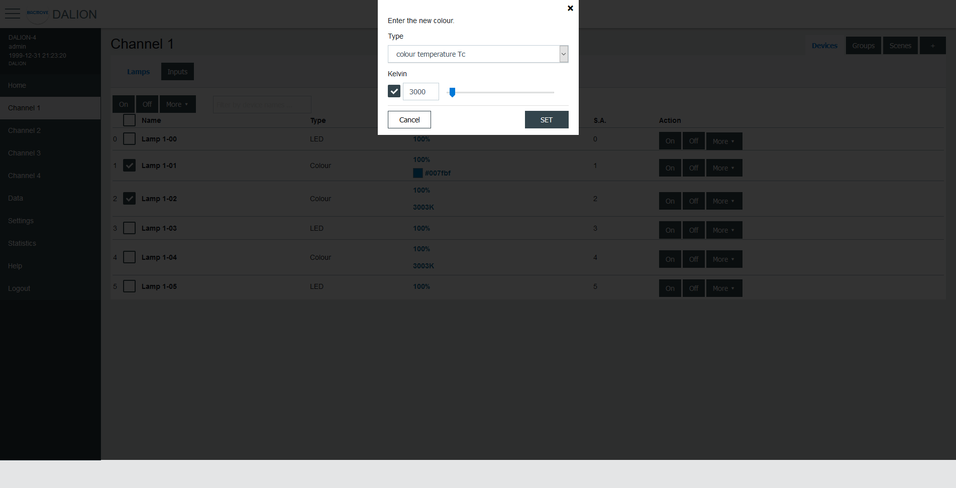
colour temperature Tc
| Name | Unit | Minimum | Maximum | Default | Description |
|---|---|---|---|---|---|
| Kelvin | Kelvin | 16 (1) | 1 000 000 (1) | Colour temperature in Kelvin |
(1) The minimum and maximum Kelvin are also limited by the warmest and coolest parameters.
primary N
| Name | Unit | Minimum | Maximum | Default | Description |
|---|---|---|---|---|---|
| Primary 0-5 | 0 | 65534 | Primay value |
RGBWAF
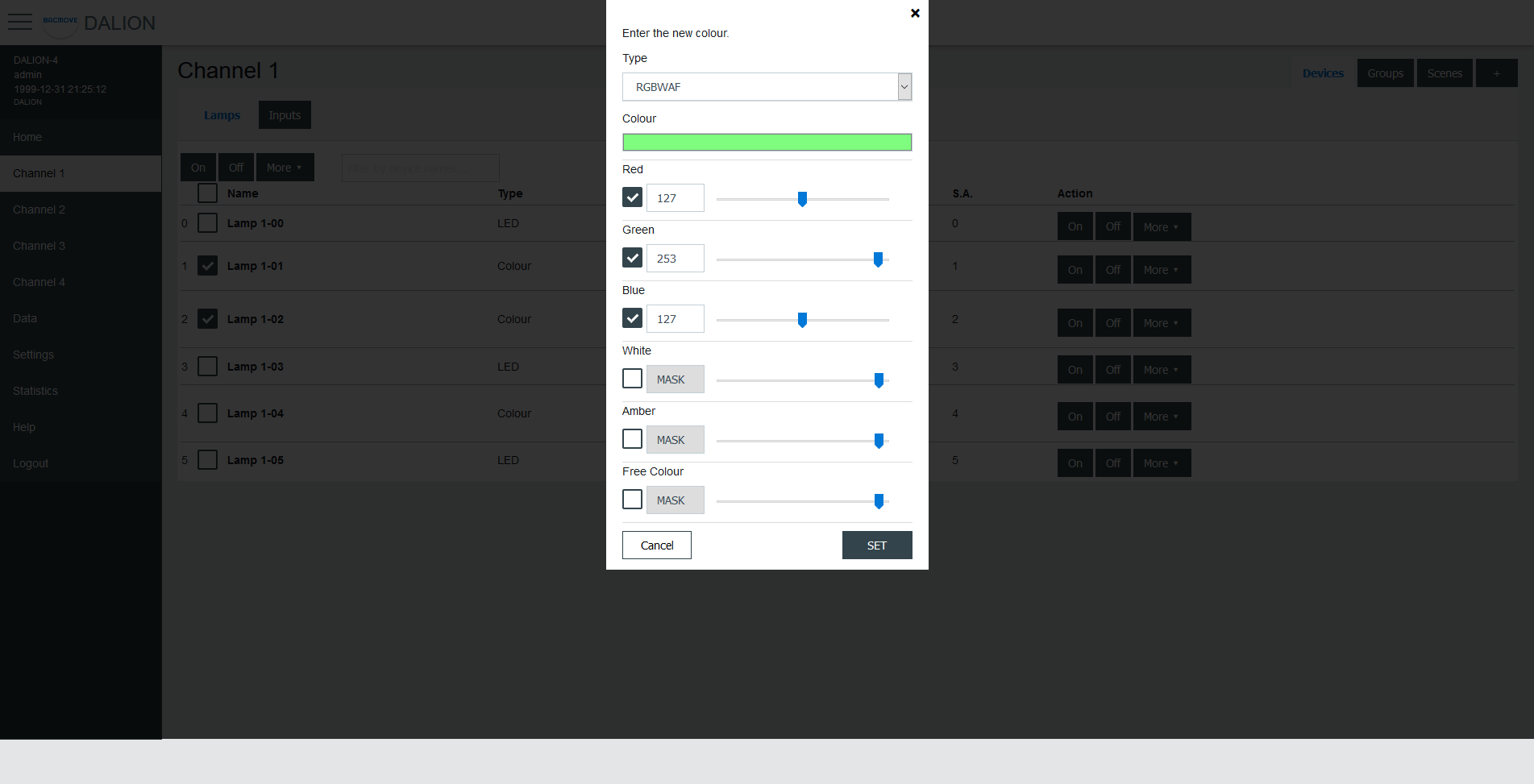
| Name | Unit | Minimum | Maximum | Default | Description |
|---|---|---|---|---|---|
| Colour Preview (1) | RGB | Clicking on the colour will open the browser colour picker. | |||
| Red | 0 | 254 | Red colour value | ||
| Green | 0 | 254 | Green colour value | ||
| Blue | 0 | 254 | Blue colour value | ||
| White | 0 | 254 | White colour value | ||
| Amber | 0 | 254 | Amber colour value | ||
| Freecolour | 0 | 254 | Freecolour colour value |
(1) Colour is for demonstration purposes only, the resulting lamp colour may be different.
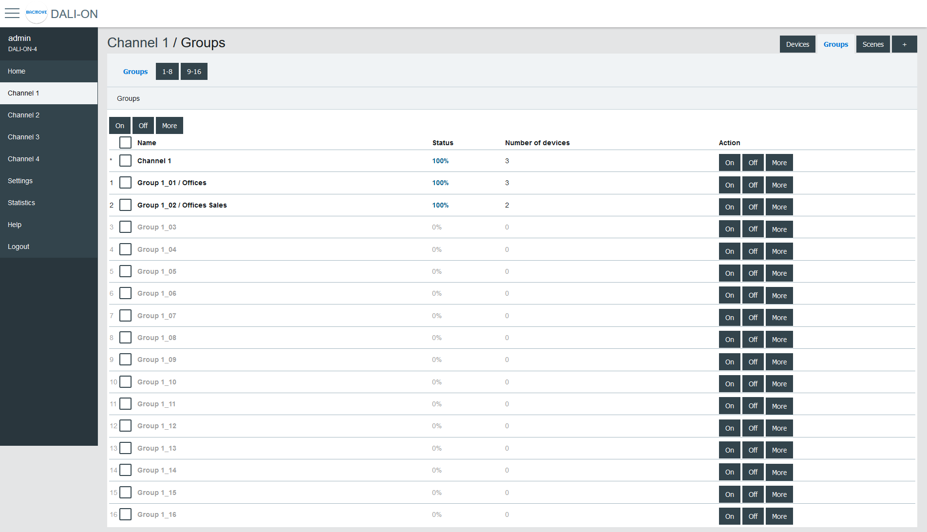
Groups
There are 16 groups for the lamps and each lamp can be part of any combination of the 16 groups. This page allows visualization and control of the groups.
The first line is indicated by a * and is the channel. The underlying lines are numbered for the 16 groups.
It is possible to:
- turn On or Off the group
- Set Level of the group intensity
- Recall, Store and Delete the group scenes
By clicking on a group row, the Group Parameters page opens.
Group Parameters
This page allows the configuration of group parameters.
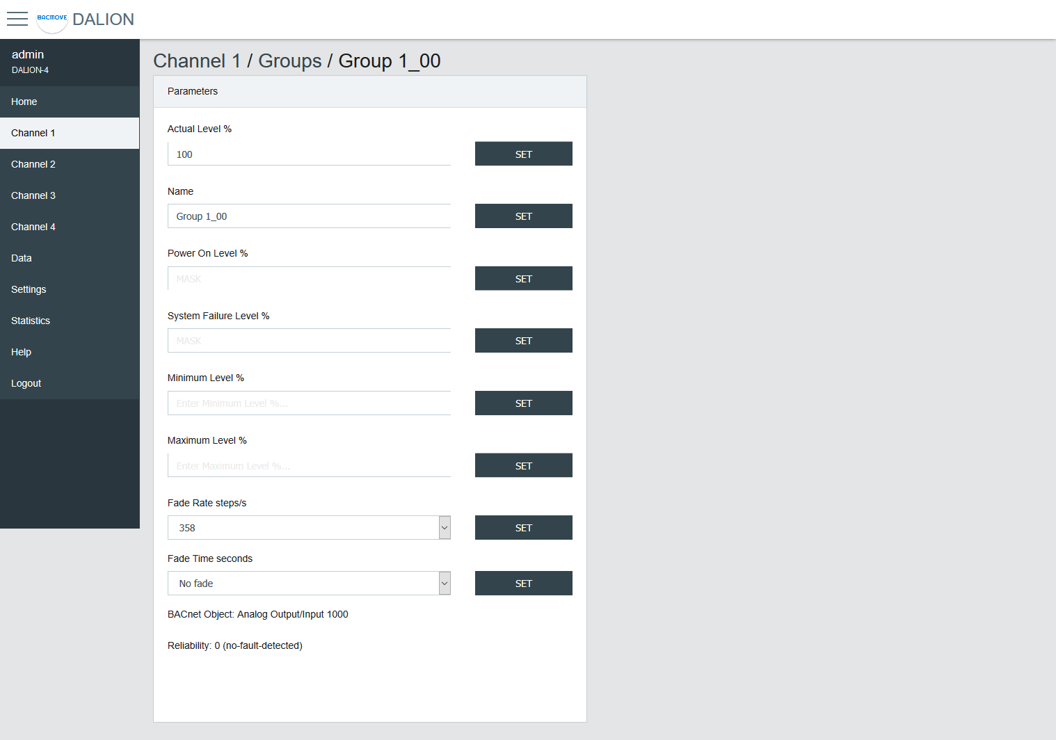
| Name | Unit | Minimum | Maximum | Default | Description |
|---|---|---|---|---|---|
| Actual Level | Percent | 0% | 100% | Actual group intensity | |
| Name | String | 32 characters | Name of the group | ||
| BACnet Object | String | BACnet object identifier of the group | |||
| Reliability | String | BACnet reliability of the group object | |||
| BAS Timeout Command | Choice | No Command | The command executed when communication is lost with another BACnet device (BAS). No Command, Off, On or Timeout Level. |
Group names provide textual identification for each group. The intensity level of the groups can be changed. Once it is modified, all lamps in the group must reach the same brightness level.
Certain parameters of the DALI lamps can be sent to all the lamps which are part of the group.
| Name | Unit | Minimum | Maximum | Default | Description |
|---|---|---|---|---|---|
| Power On Level | Percent | 0% | 100% | 100% | Level of intensity after a power on |
| System Failure Level | Percent | 0% | 100% | 100% | Level of intensity when system failure |
| Minimum Level | Percent | 0.1% | 100% | 100% | Minimum level of intensity |
| Maximum level | Percent | 0.1% | 100% | 100% | Maximum level of intensity |
| Fade Rate | Choice | 2.8 | 358 | 44.7 | Fade rate in steps per second |
| Fade Time | Choice | No Fade | 90.5 | No Fade | Fade time in seconds |
| Dimming Curve | Choice | Logarithmic | Linear | Logarithmic | Dimming curve |
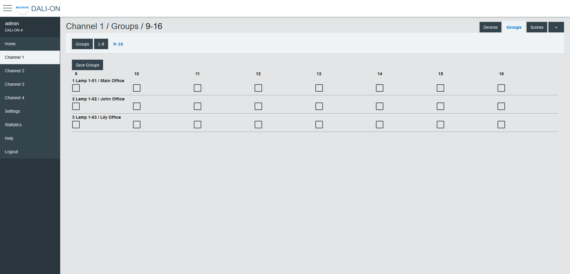
Groups 0-7 / 8-15
For easy visualization and assignment of the 16 groups, they are separated in views of eight groups (i.e., Groups 0-7 and Groups 8-15).

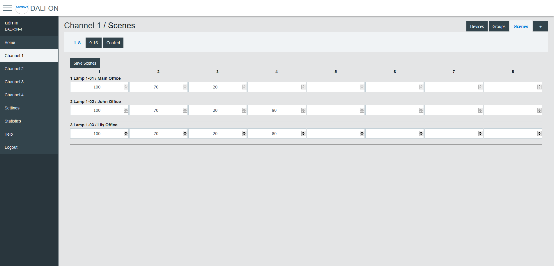
Scenes
Each lamp has 16 scenes. A scene is a level of light intensity in percentages. The value of a scene can also be left empty. Scenes control can be sent to a single lamp, a group of lamps, or the entire DALI channel. When a scene is recalled, all the addressed lamps are invited to dim their brightness at the same brightness level.
For lamps with colour control (i.e., DT8), the 16 scenes can also recall the colour levels. The configuration of the scene colour levels should be performed in the Colour page of each lamp.
Scenes Control
Scenes can be recalled, stored or deleted. Once the desired group or broadcast destination is selected and the Recall, Store or Delete action is also selected, one of the 16 scenes can be performed.
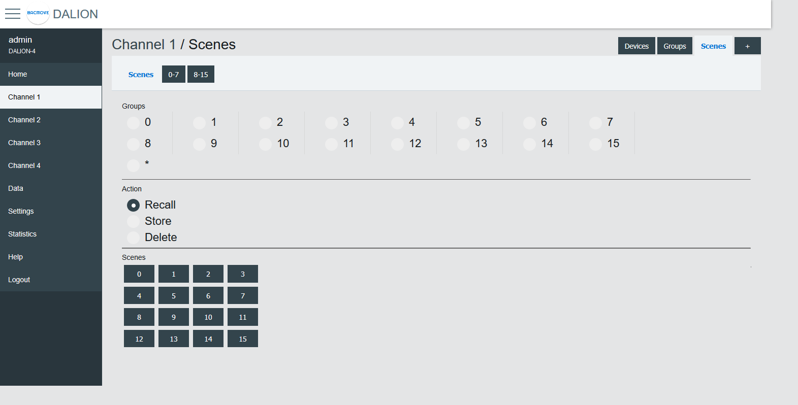
Scenes 0-7 / 8-15
For easy visualization and configuration of the 16 scenes, they are separated in views of eight scenes (i.e., Scenes 0-7 and Scenes 8-15).

Memory Bank
This page allows read, editing and writing DALI memory banks of lamps and DALI-2 input devices.
Inputs
This page displays the list of commissioned DALI light sensors, occupancy sensors and buttons. The list provides a descriptive Name of each input device as well as other information like occupancy state, light value, types and short address.
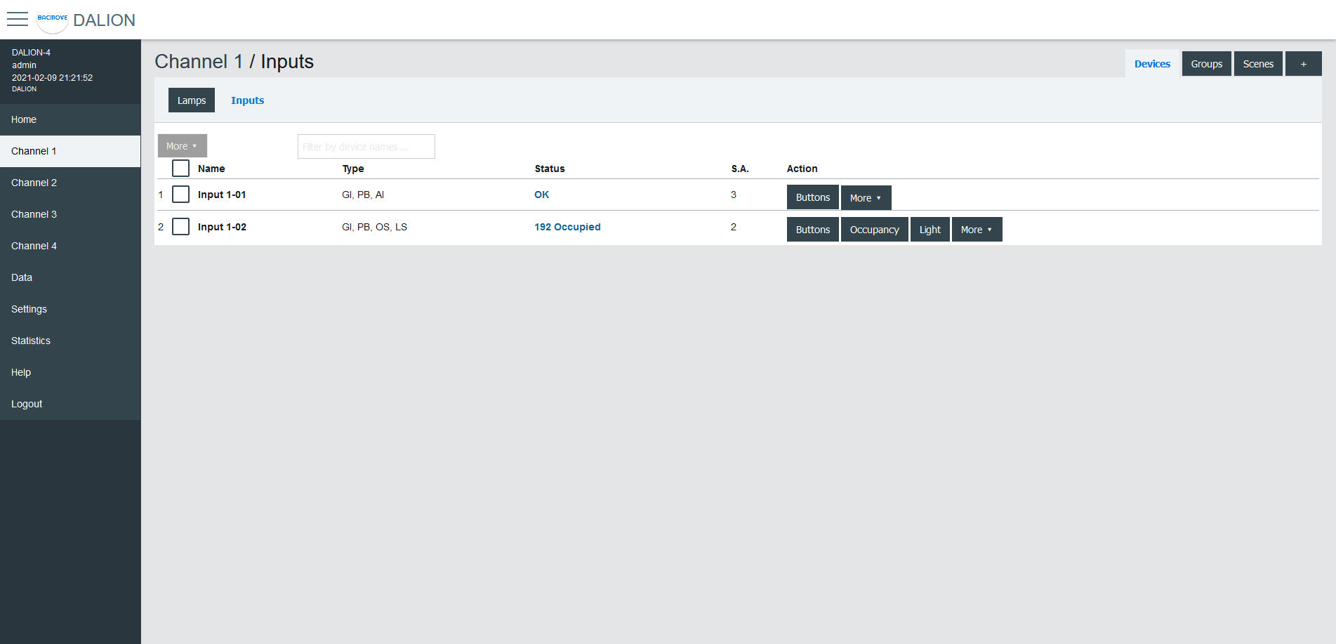
Inputs devices can identify themselves with the Identify button.
The 🛇 icon indicates that Buttons or Occupancy commands are prohibited. See the network properties Allowed_Command or Buttons_Allowed_Command for more information.
By clicking on an input row, the Input Parameters page opens.
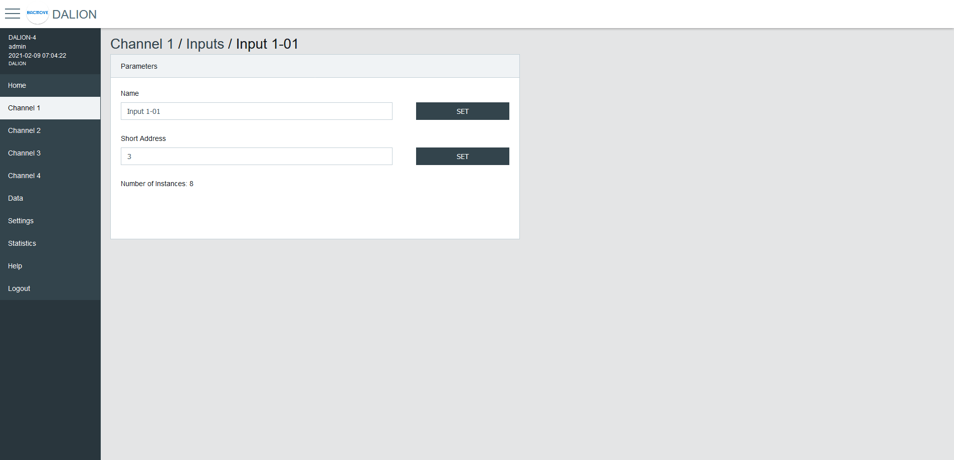
Input Parameters
This page allows the configuration of input parameters.
Parameters
| Name | Unit | Minimum | Maximum | Default | Description |
|---|---|---|---|---|---|
| Name | String | 32 characters | Name of the device | ||
| Short Address | Number | 0 | 63 | The short address | |
| Number of instances | Number | 1 | 32 | Displays the number of instances |
Instances Value
Display of the values of the input instances.

Command Allowed
Display and modification of the allowed commands for the occupation and button inputs.

Buttons
Each input device support up to 32 button instances. The command and destination for each instance are configurable by clicking on an instance row.
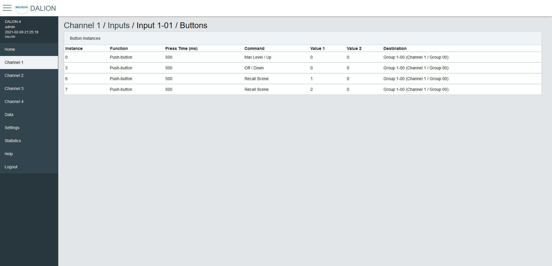
Button Parameters
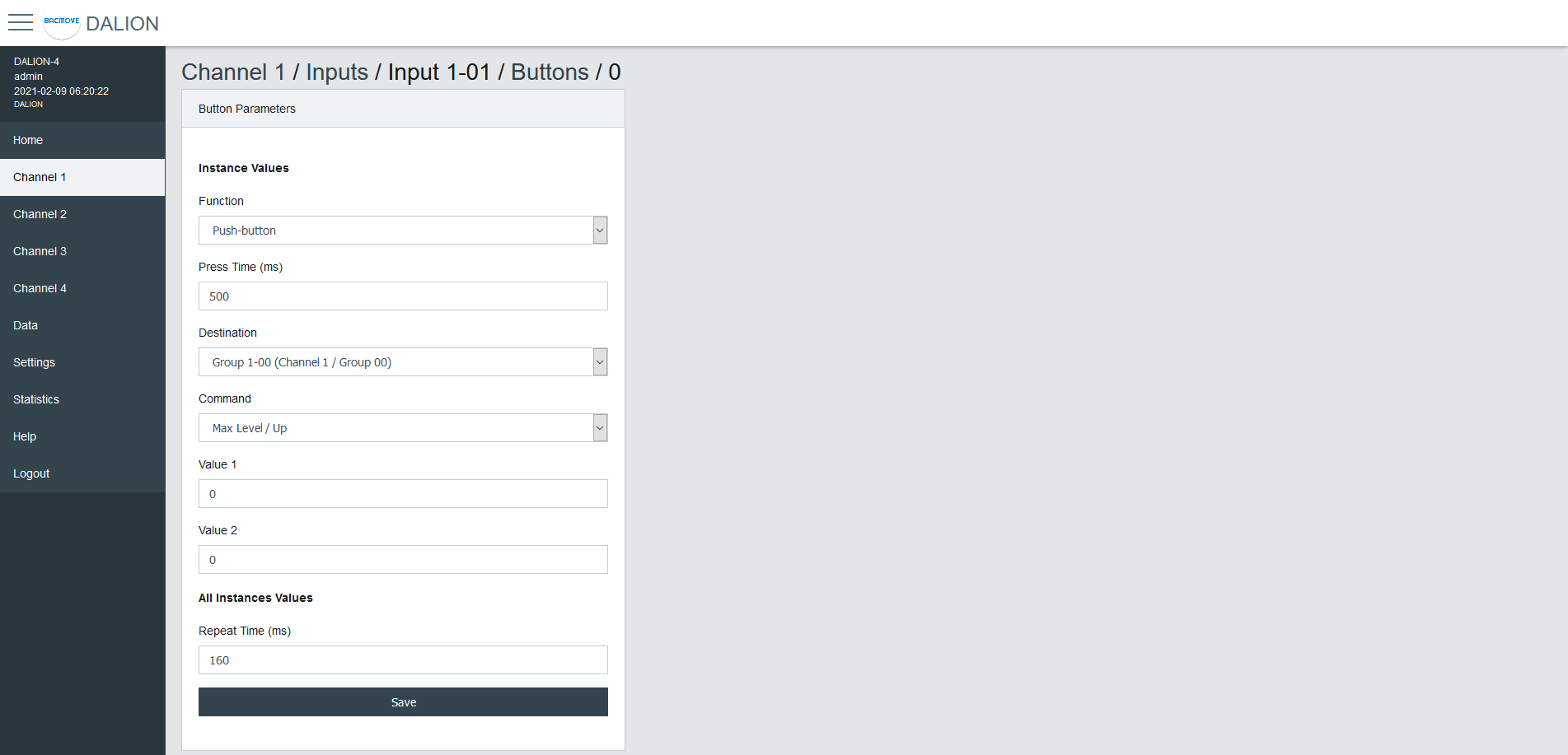
| Name | Description |
|---|---|
| Function | Push-button or Switch |
| Press Time | Press time in milliseconds |
| Destination Type | Type of the Destination |
| Destination | Destination of the command |
| Command | Choice of the button command |
| Value 1 | First value of the command |
| Value 2 | Second value of the command |
Function
| Name | Description |
|---|---|
| Push-button | Actuated when the button is temporarily pressed |
| Switch | Actuated when the button position is toggled |
Push-button for momentary contact, like a wall push button.
Switch for maintained contact, like an occupancy sensor or a photocell.
Press Time
The time in milliseconds before registering a button press.
Repeat Time (ms)
The time in milliseconds between repeated commands. This parameter is the same for all instances of the same device.
Destination Type
The destination type allows to determine wich destinations and commands are available to the button configuration.
| Name |
|---|
| Group, Channel, RLC |
| Lamp |
| Commander |
| Commanders |
Group, Channel, RLC
Allows commanding a DALI group, a DALI channel, or a Room Light Control.
Room Light Control commands are prefixed with "RLC:".
Lamp
Allows commanding a DALI lamp.
Commander
Allows starting or stopping a Commander.
Commanders
Allows starting or stopping a Commander.
Destination
The destination depends on the selected Destination Type.
Command - Group, Channel, RLC, Lamp
Push-button
| Name | Short Press | Long Press | Long Press Repeat |
|---|---|---|---|
| Disabled | |||
| Direct Value | Direct Value Value 1 % | ||
| On | Recall Max Level | ||
| On / Up | Recall Max Level | On and Step Up | Up |
| Off | Off | ||
| Off / Down | Off | Step Down and Off | Down |
| Min Level | Min Level | ||
| Min Level / Down | Min Level | Step Down and Off | Down |
| Recall Scene | Recall Scene Value 1 0-15 | ||
| Recall Scene / Up | Recall Scene Value 1 0-15 | On and Step Up | Up |
| Recall Scene / Down | Recall Scene Value 1 0-15 | Step Down and Off | Down |
| On / Off | Toggle between Recall Max Level and Off | ||
| Last Level | Recall Last Level | ||
| Last Level / Up | Recall Last Level | On and Step Up | Up |
| Last Level / Off | Toggle between Last Level and Off | ||
| On / Off, Up / Down | Toggle between Recall Max Level and Off | Toggle between On and Step Up and Step Down and Off | Toggle between Up and Down |
| Last Level / Off, Up / Down | Toggle between Recall Last Level and Off | Toggle between On and Step Up and Step Down and Off | Toggle between Up and Down |
| Direct Value / Off, Up / Down | Toggle between Direct Value Value 1 % and Off | Toggle between On and Step Up and Step Down and Off | Toggle between Up and Down |
| Recall Scene / Off, Up / Down | Toggle between Recall Scene Value 1 0-15 and Off | Toggle between On and Step Up and Step Down and Off | Toggle between Up and Down |
| RLC: Occupancy - Unoccupied | Toggle occupancy state, 1 is unoccupied. | ||
| RLC: Occupancy - Occupied | Toggle occupancy state, 1 is occupied | ||
| RLC: Daylight Harvesting - Stop | Stop daylight harvesting | ||
| RLC: Daylight Harvesting - Start | Start daylight harvesting | ||
| RLC: Demand Response - Stop | Stop demand response | ||
| RLC: Demand Response - Start | Start demand response |
Switch
| Name | Open switch | Close switch |
|---|---|---|
| Disabled | ||
| Direct Value | Direct Value Value 2 % | Direct Value Value 1 % |
| On | Recall Max Level | |
| On / Up | Recall Max Level | |
| Off | Off | |
| Off / Down | Off | |
| Min Level | Min Level | |
| Min Level / Down | Min Level | Min Level |
| Recall Scene | Recall Scene Value 1 0-15 | Recall Scene Value 2 0-15 |
| Recall Scene / Up | Recall Scene Value 1 0-15 | Recall Scene Value 2 0-15 |
| Recall Scene / Down | Recall Scene Value 1 0-15 | Recall Scene Value 2 0-15 |
| On / Off | Off | On |
| Last Level | Recall Last Level | |
| Last Level / Up | Recall Last Level | |
| Last Level / Off | Off | Recall Last Level |
| On / Off, Up / Down | Off | On |
| Last Level / Off, Up / Down | Off | Recall Last Level |
| Direct Value / Off, Up / Down | Off | Direct Value Value 1 % |
| Recall Scene / Off, Up / Down | Off | Recall Scene Value 1 0-15 |
| RLC: Occupancy - Unoccupied | Occupied | Unoccupied |
| RLC: Occupancy - Occupied | Unoccupied | Occupied |
| RLC: Daylight Harvesting - Stop | Start daylight harvesting | Stop daylight harvesting |
| RLC: Daylight Harvesting - Start | Stop daylight harvesting | Start daylight harvesting |
| RLC: Demand Response - Stop | Start demand response | Stop demand response |
| RLC: Demand Response - Start | Stop demand response | Start demand response |
Command - Commander
| Name | Short Press | Long Press | Long Press Repeat |
|---|---|---|---|
| No Command | |||
| Start | Start the commander in the Destination | ||
| Stop | Stop the commander in the Destination |
Command - Commanders
| Name | Short Press | Long Press | Long Press Repeat |
|---|---|---|---|
| No Command | |||
| Start Commander NN | Start the commander NN | ||
| Stop Commander NN | Stop the commander NN |
Value 1
First value of the command.
Value 2
Second value of the command.
Occupancy Sensor
Each input device supports up to one occupancy sensor instance.
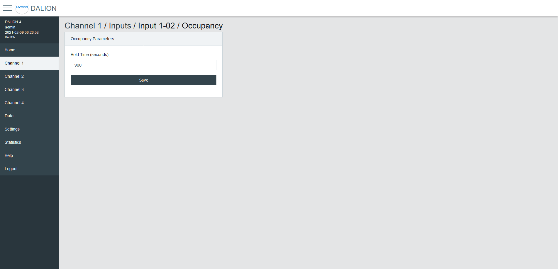
| Name | Unit | Minimum | Maximum | Default | Description |
|---|---|---|---|---|---|
| Hold Time | Seconds | Hold time in seconds |
Light Sensor
Each input device supports up to one light sensor instance.
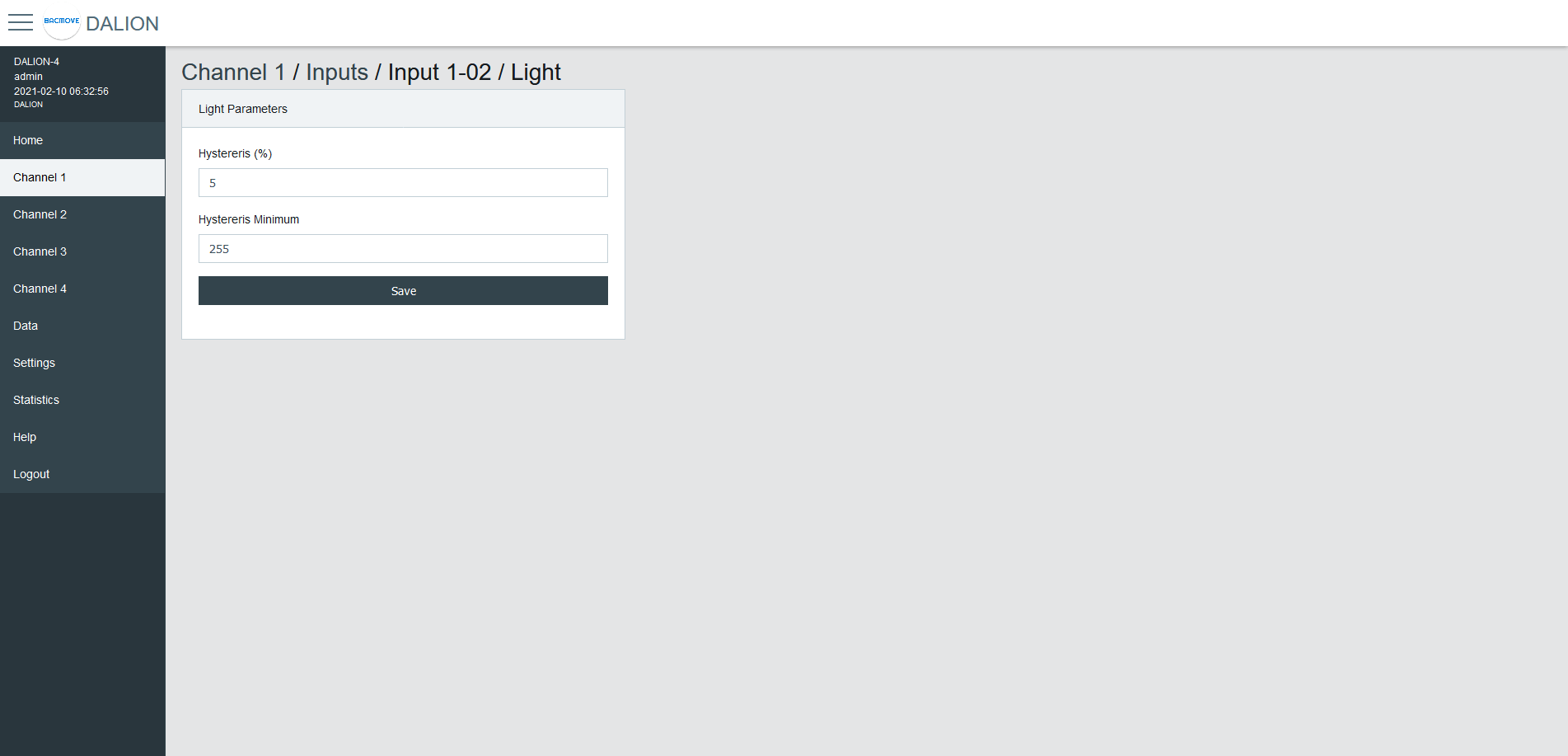
| Name | Unit | Minimum | Maximum | Default | Description |
|---|---|---|---|---|---|
| Hysteresis | Hysteresis in percentage | ||||
| Hysteresis Minimum | Hysteresis minimum |
To prevent flooding the DALI network with an excessive number of events triggered by minor changes in illuminance levels, a hysteresis band is present in the light sensor.
The hysteresis band is determined as the greater of the following values:
-
The Hysteresis in percentage of the sensor internal current illuminance level.
-
The Hysteresis Minimum.
Hysteresis
This is a percentage of the current sensor internal illuminance level.
The valid values are from 0 to 25 percent.
Hysteresis Minimum
The minimum hysteresis.
The valid values are from 0 to 255.
Light Sensor Calibration
Light sensor calibration involves using a lux meter to measure the ambient light intensity. By comparing the value of the sensor with the lux meter reading, you can adjust the sensor to ensure accurate and consistent measurements. This process ensures that the output of the sensor corresponds accurately to the actual light intensity in lux.
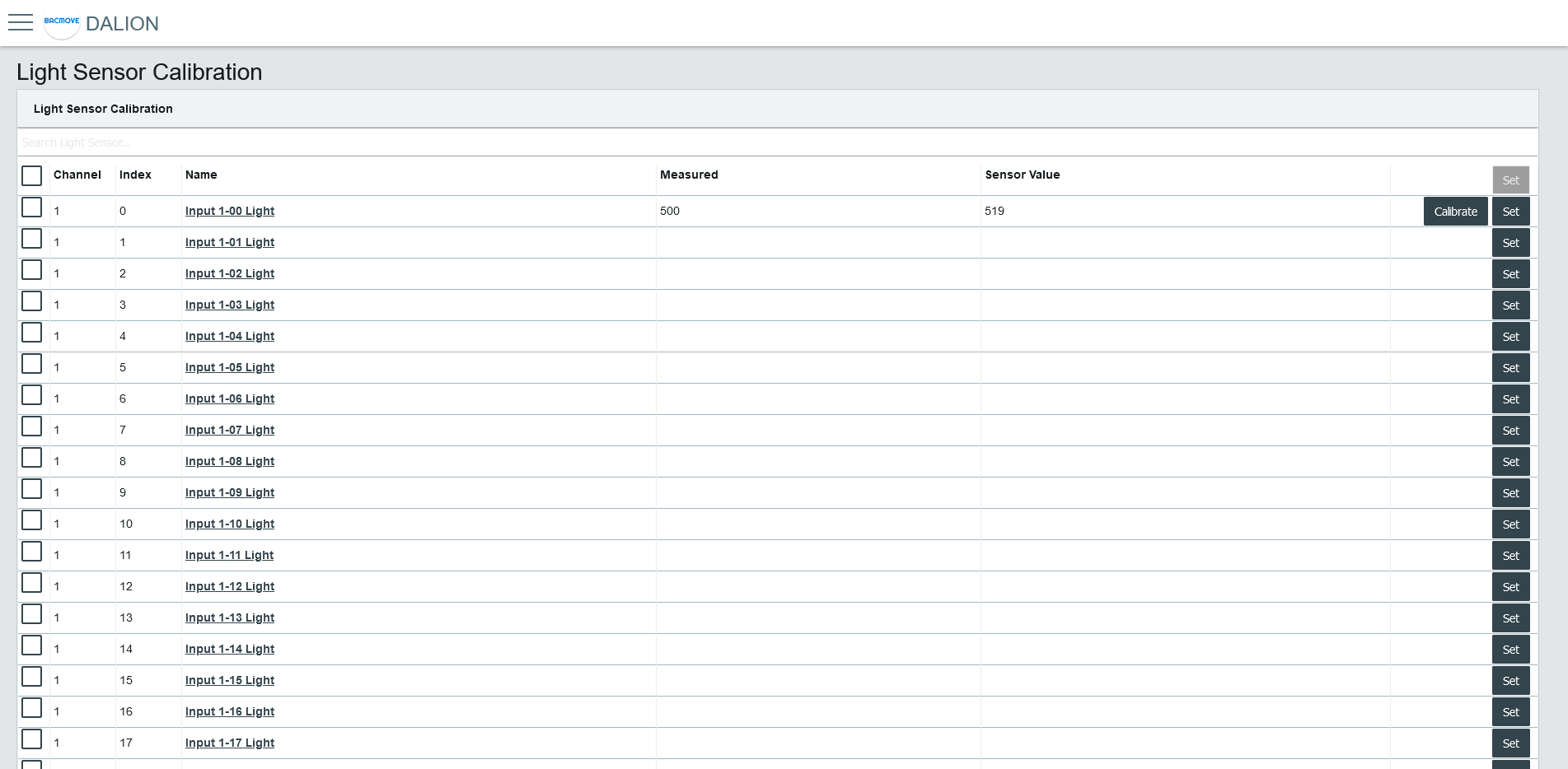
Light Sensors List
It list the calibration for each light sensor.
Collumns
####### Checkbox
Allows the manual calibration of the multiple selected light sensors.
####### Channel
The light sensor channel number, 1 to 4.
####### Index
The light sensor index number, 0 to 31.
####### Name
The light sensor name.
####### Measured
The value measured with a lux meter for calibration.
####### Sensor Value
The light sensor reading value used for calibration.
####### Calibrate Button
Opens the light sensor calibration.
Enter the value obtained from the lux meter and press the Calibrate button.
The Reset button clears the calibration, allowing the use of the light sensor value without calibration.

####### Set Button
Opens the manual calibration for the light sensor.
Enter the value obtained from the lux meter and the light sensor reading. Then, press the Set button.
The Reset button clears the calibration, allowing the use of the light sensor value without calibration.

Addition of DALI devices
The button "+" is used to search for non-commissioned devices.
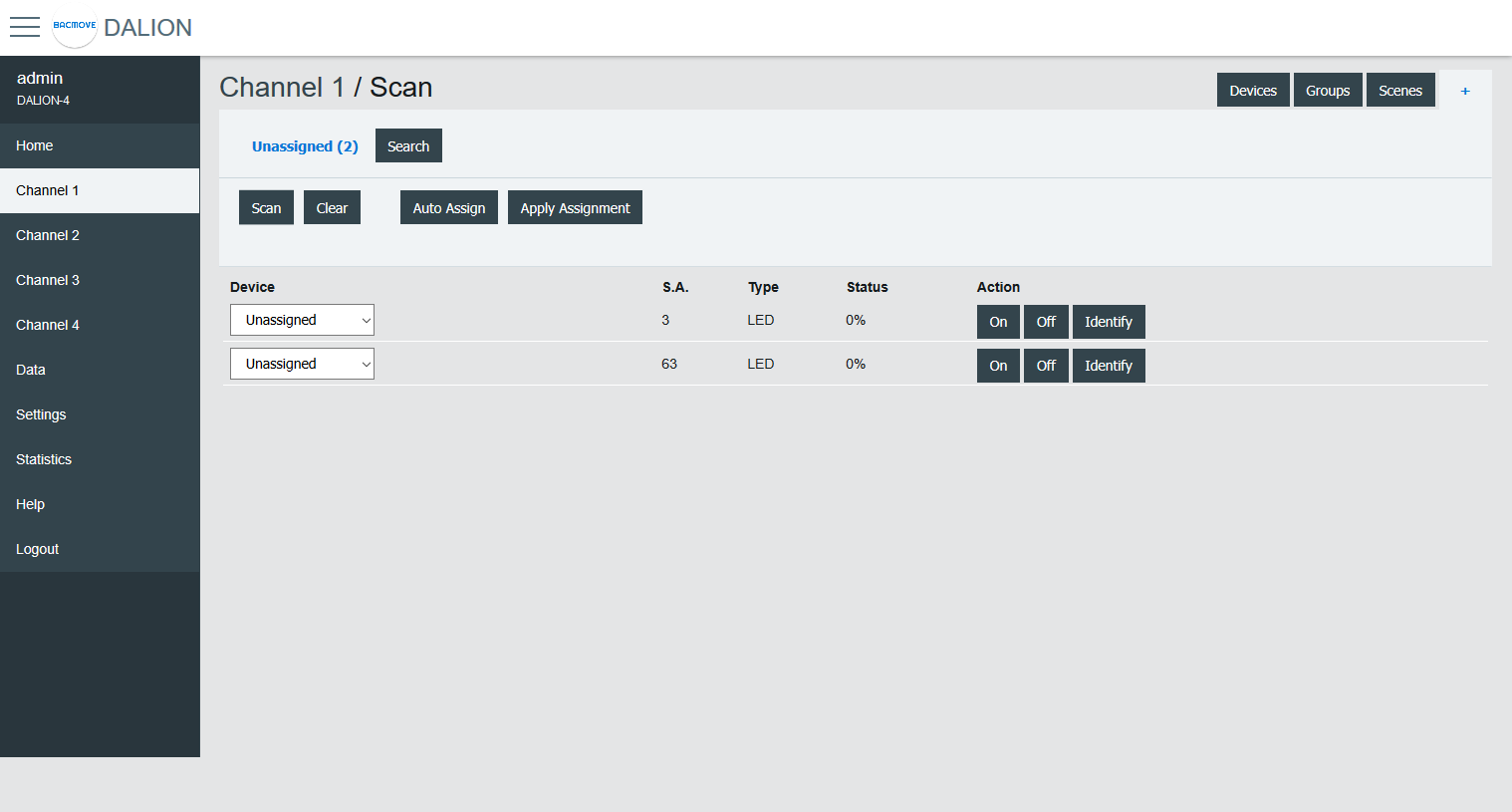
Unassigned Devices
After scanning a channel, the page displays the non-commissioned devices found on the network. The buttons allow turning On, Off and to Identify the lamp by cycling it between its minimum and its maximum of intensity.
The Scan button allows starting a scan on the DALI channel for unassigned devices.
The Clear button allows clearing the list of unassigned devices.
The Auto Assign button automatically assigns lamps to a lamp index.
The Apply Assignment button assign lamps to a selected lamp index.
Assignment
There are three ways of assigning the DALI devices.
Auto Assign
The lamps are automatically assigned to a lamp index.
Apply Assignment
The selected assignment is applied.
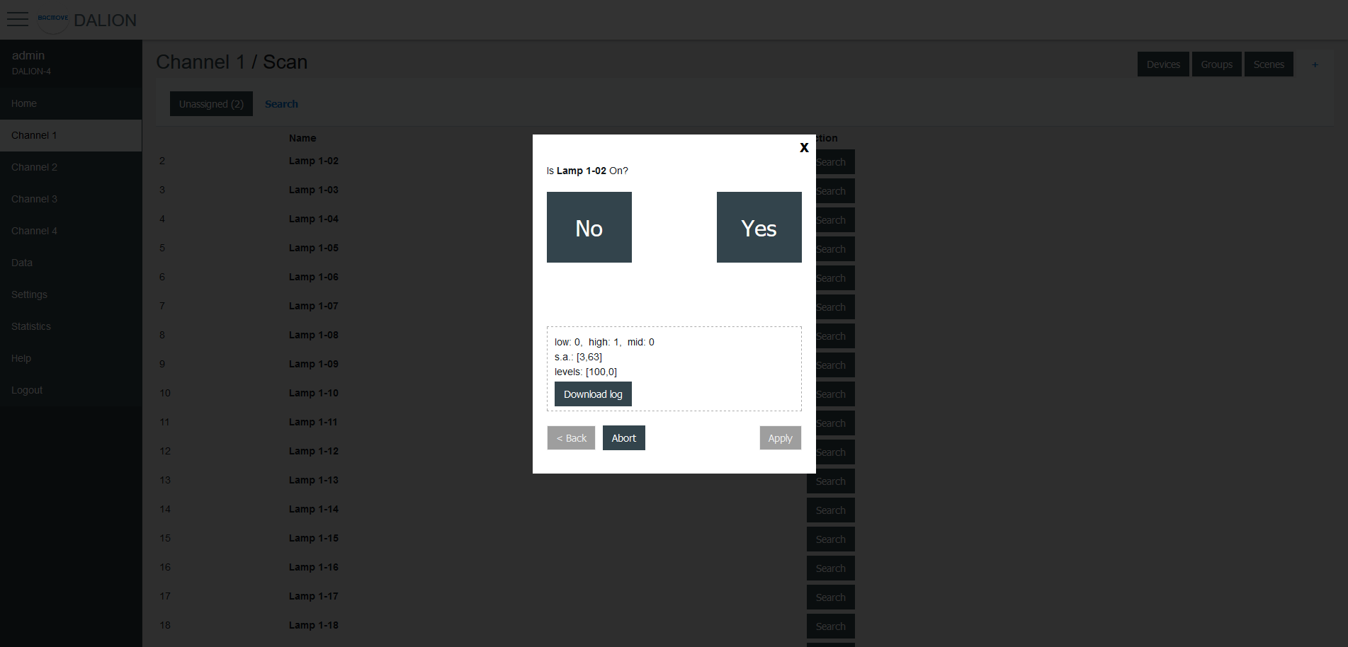
Search
The available lamps can be searched. By pressing the Search button next to a lamp, a search by a half-interval search means is launched to find the lamp. Half of the lamps are turned Off, while the other half is turned On, the user must answer No or Yes if the desired lamp is On. This process is repeated until only the desired lamp is On.
Once the search is complete, the user can enter a name for the lamp and Apply the assignment.